Understand the replacement part workflow: inspect for damage and improve component design and manufacturability effectively.
From Replacement Part to Finished Component: A Modern Workflow
Estimated reading time: 4 minutes
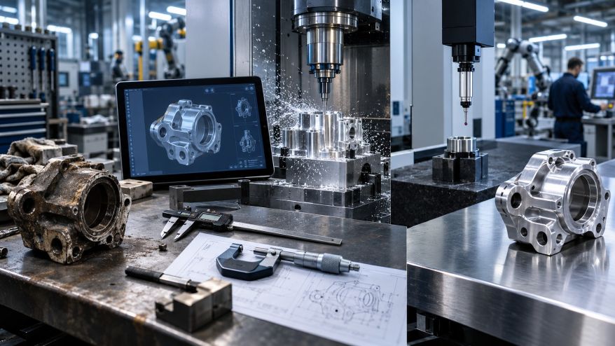
When a machine component breaks, the immediate priority is usually straightforward: replace it and get the equipment running again. But a replacement part does not always need to be an exact copy of the original. In many cases, the replacement part workflow creates an opportunity to improve the component’s design, durability, fit, or manufacturability.
Begin With a Detailed Assessment of the Original Part
The first step is understanding what the replacement part actually does.
A visual inspection can reveal obvious damage, but it may not explain why the component failed. Look for cracks, deformation, excessive wear, corrosion, loose interfaces, and areas showing repeated stress.
The surrounding assembly should also be examined.
Document:
- Overall dimensions
- Mounting points
- Interfaces with other components
- Visible damage
- Wear patterns
- Material characteristics
- Operating environment
- Approximate service life
- Failure conditions
The goal is to understand both the part and the system around it.
For safety-related machinery, the assessment should also account for applicable workplace requirements. The Occupational Safety and Health Administration’s machine guarding guidance provides background on protecting workers from hazards associated with machinery.
Select a Suitable Manufacturing Process
The manufacturing method should be chosen based on geometry, material, quantity, tolerances, and intended use.
Several options may be appropriate depending on the component.
Thermoforming
For suitable plastic components, thermoforming can be considered when the design involves formed sheets or shells. Engineers evaluating custom thermoforming services should consider the part’s geometry, material requirements, production quantity, tooling approach, and dimensional needs rather than focusing on the process alone.
CNC machining
Machining is very useful for parts requiring precise dimensions and durable materials. It can be suitable for metal brackets, shafts, plates, adapters, fixtures, and other components where dimensional accuracy is important.
Also Read: CNC machining for hardware startups
Additive manufacturing
3D printing can be useful for prototypes, custom fixtures, low-volume components, and geometries that would be difficult to produce using conventional processes.
Injection molding
Injection molding can become practical for higher-volume plastic components where tooling costs can be justified by production quantities.
Also Read: What is Insert Molding?
Capture Accurate Measurements
Once the replacement strategy is established, accurate measurements become critical.
Callipers, micrometres, gauges, and other common checking tools can be used to measure basic parts of things. Coordinate measuring or 3D scanning may be needed for more complicated parts.
It’s not enough to just measure the length, width, and height of something. Along with these, engineers should particularly pay attention to:
- Hole diameters
- Hole spacing
- Wall thickness
- Angles
- Radii
- Thread specifications
- Mating surfaces
- Alignment features
- Critical clearances
It is useful to distinguish between critical and non-critical dimensions. A mounting hole that determines the position of a sensor may require much tighter control than an external surface that has no functional purpose.
Create a Digital Model
After measurement, the physical part can be translated into a digital model.
Computer-aided design provides a useful bridge between reverse engineering and manufacturing. The model can capture dimensions, interfaces, material assumptions, and design changes in a format that can be reviewed and revised.
Replacement Part Workflow: Conclusion
The modern replacement-part workflow goes beyond copying a damaged component. It provides a structured path from identifying a failed part to developing, testing, and documenting a finished component.
The most effective replacement part process start with understanding why the original part existed, and also how it performed. Then, accurate measurements, digital modelling, the right ways to make things, prototyping, real-life testing, and thorough documentation help turn that understanding into a replacement that works well.
FAQs: Replacement Part Workflow
1. What is reverse engineering in replacement part workflow?
In reverse engineering, you look at a part that already exists to figure out its size, shape, materials, connections, and how it works. After that, the data can be used to make a digital model and design a replacement in case the original drawings or specs are lost.
2. Should a replacement part always copy the original design?
No. Reproducing the original design might be fine if it worked well, but redesigning might be better if it kept breaking down, used old materials, had production issues, or had interfaces that didn’t work with newer devices. Before making any changes, they should be compared to the part’s actual operating needs.
3. Why is prototyping important before producing a replacement part?
Engineers can test fit, alignment, clearance, assembly, and functionality with prototypes before committing to full production. It can find problems that are hard to see from measures or CAD models alone, so changes can be made faster and with less trouble.
Reviewed by Dinesh Joshi on October 6, 2026Edited by Juveriya Khan
Note: The article includes external links to third-party services; readers should independently evaluate any referenced platforms before engaging.
- Author
- Latest Posts

Daniel Martin loves building winning content teams. Over the past few years, he has built high-performance teams that have produced engaging content enjoyed by millions of users. After working in the Aviation industry for ten years, today, Dani applies his international team-building experience at organiclinkbuilders.com to solving his client’s problems. Dani also enjoys photography and playing the carrom board.