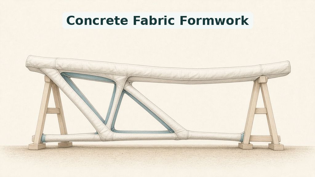
A school desk can hide the effort needed to support a heavy load. Its frame sends weight toward the floor through selected routes, rather than solid walls. Similarly, concrete beams need material along useful paths, not necessarily throughout a rectangular block. Teams at MIT and Boston University have explored that idea with sewn molds. Their concrete fabric formwork turns flat cotton pieces into containers for branching beams. As a result of this, the demonstration needed no machine-carved mold. The team cast three beams, each three meters long, or roughly ten feet. Compared with a standard beam, it used about one-third the concrete and half the steel. At the same time, limited testing leaves key safety questions for later work. The official MIT announcement describes the study in the Journal of Building Engineering. For this reason, the achievement concerns casting and early testing, not building approval.
Construction often starts with a mold holding wet concrete until it hardens. Engineers call that short-term container formwork, whether it uses wood, steel, or textile. However, intricate computer designs can demand expensive molds that defeat their savings in raw materials. In contrast to that, a sewn cotton container offers a lightweight casting route. MIT describes existing alternatives that include specialized printers and molds shaped by machines. Those tools can limit access where builders lack equipment or budgets. At the same time, fabric introduces a problem that rigid containers largely avoid. Wet concrete stretches the cloth and pulls loose surfaces downward. Therefore, a carefully drawn beam may emerge with a different shape than intended. The Boston University project page identifies casting and cost as central research challenges. For this reason, the team linked structural design directly with software that makes sewing patterns.
Fabric Formwork Must Balance Flow And Shape
Lead author Mark Hellrich at MIT faced a practical challenge: getting concrete through narrow passages. His team used a moderately wet, sand-rich mix with small stones. Because woven cotton lets water seep through, an overly runny mix loses water. At the same time, that mix presses harder against the cloth and changes its shape. The team packed each layer by hand, then tapped and kneaded the fabric. Consequently, flexible walls helped move concrete through the beam’s connected routes. In contrast to that, rigid molds would need a vibrator for this shape. That tool shakes fresh concrete to help remove trapped pockets of air inside. However, easier packing did not make the cloth behave like a fixed shell. The beam bottoms sagged, while angled legs folded slightly inward during casting. For this reason, useful shape control requires attention to both pattern design and placement.
How Sewn Concrete Molds Follow Load Paths
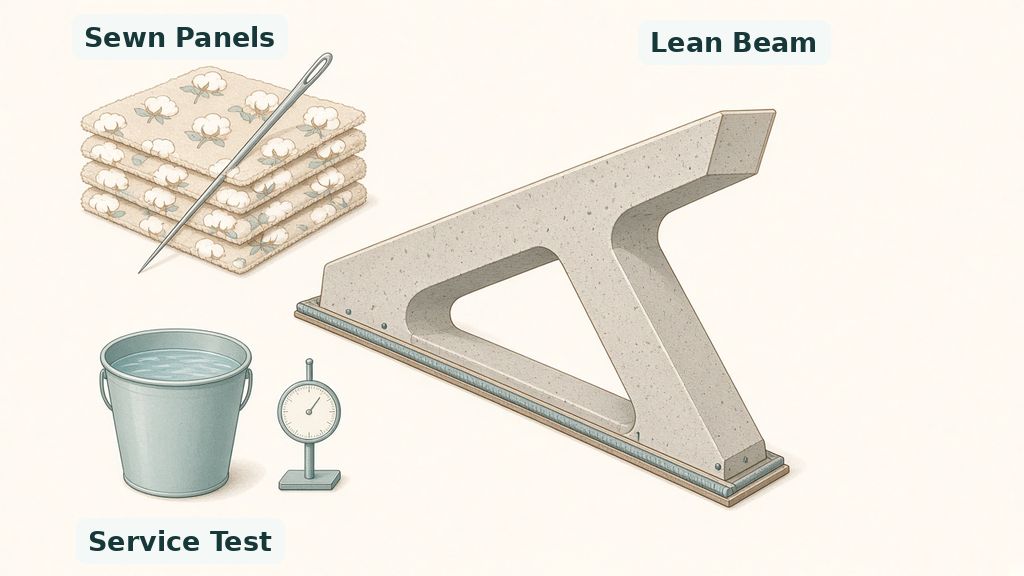
A beam transfers forces through its body toward its supports. Compression means squeezing; tension means pulling, and concrete handles the former much better. Therefore, steel reinforcement supplies the pulling resistance that the concrete alone cannot provide. As a result of this, the team designed the reinforcement and concrete together. Graphic statics maps forces using diagrams, helping engineers choose a workable steel route. Topology optimization searches for useful concrete locations within the design space. In other words, the computer removes material where it does little useful work. The university engineering report describes a top section, angled legs, and thin bottom section. Meanwhile, the bottom section contains steel taking the pulling forces. The gaps reflect choices about where to place material, rather than decoration added after design. For this reason, the branching outline connects directly with the work each material performs.
Steel Guides The Reinforcement Route
Computer optimization can generate shapes that challenge people bending steel bars. The team first used graphic statics to keep the steel layout easy to build. Next, it shaped the bar to share the load evenly along its length. At the same time, the slower optimization method could place concrete more freely. Those roles explain why the workflow combines tools rather than choosing one. Consequently, a simpler steel path guides the search for a leaner concrete body. The design still needs both materials, despite its large gaps. In contrast to that, simply removing concrete from an ordinary beam ignores its force routes. Steel does not make every possible opening safe under every possible loading arrangement. Instead, the team compared their optimized beam with a standard design carrying the same load. Thus, the reported material savings belong to that design comparison.
Sewn Concrete Molds Start As Flat Patterns
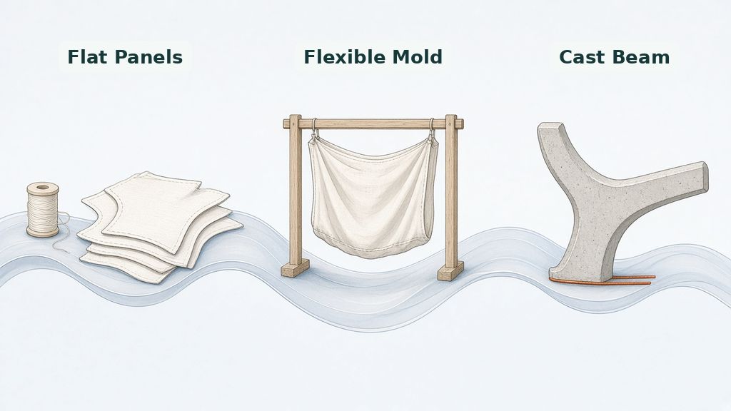
A sewing pattern turns a flat sheet into a shape with depth and volume. Here, automated pattern-making translated the three-dimensional beam into cotton pieces. Then, the team cut and sewed those pieces into a joined mold. As a result of this, digital shape reached the workshop through familiar textile operations. The process accounted for deformation, meaning the fabric’s stretching and sagging under wet concrete. A simple timber frame supported the mold during concrete placement. At the same time, the frame and pattern worked together to constrain the shape. However, the cloth still moved, so the team checked the finished beams with scans. Those measurements compared actual surfaces with the planned shape. In other words, the workflow tested casting behavior, not just an attractive computer drawing. Finally, physical beams showed where the planned shape held during casting.
What The Beam Tests Actually Show
The team produced three beams to explore how seams influence shape. Each mold targeted the same design but divided its surface differently. Specifically, the patterns used thirty-six, fifty-six, and seventy-six separate pieces of cotton fabric. At the same time, every extra piece added cutting, alignment, and sewing work. The coauthor laboratory abstract separates local detail control from overall shape control in its findings. More seams improved local control, meaning they constrained small regions more closely. However, more detailed panel divisions did not necessarily improve the entire beam’s shape match. As a result of this, the most complex mold did not always perform best. The middle pattern provided the best balance in MIT’s account. In other words, a useful seam pattern balances shape control against small sewing errors. Therefore, the study treats casting effort as an engineering choice rather than an automatic benefit.
Fig. 1: Sewing Meets Early Load Testing
Seams Trade Local Detail For Assembly Work
Smaller panels give the fabric more boundaries that restrain movement within each patch. Their seams therefore help shape details that a larger loose sheet might blur. However, joining more patches creates more chances for small errors in cutting and sewing. At the same time, those errors can add up across the complete sewn mold. A locally neater surface does not guarantee that the entire beam matches its target. Consequently, designers need to assess the whole shape alongside its small features. The team used three-dimensional scans to show that distinction after concrete hardened. In contrast to that, judging the mold only before pouring would miss wet-load deformation. The top surfaces stayed close to the planned design, despite movement elsewhere. Instead, the main shape changes included bottom sag and slight inward movement of angled legs. Thus, the next design decisions must consider global shape alongside local detail.
Fig. 2: Flat Panels Become A Flexible Mold
Service Loads Do Not Establish Failure Strength
The team load-tested one beam by stacking water-filled buckets across its upper surface. Gauges tracked its downward movement, called deflection, as loads changed. Importantly, the test reached about thirty percent of design load, roughly three-tenths of that target. As a result of this, the experiment examined service conditions rather than failure. At the center, measured deflection differed by about two percent from the computer prediction. That close comparison concerns bending under the tested loads, not the beam’s highest load. In other words, matching a predicted movement does not establish a safe breaking load. The proof of concept therefore supports further investigation without supplying building-code approval for construction. However, MIT reports that the team next wants to test multiple beams to failure. Such experiments would examine behavior beyond the limited service-load demonstration. For this reason, readers should separate model agreement from evidence of breaking strength.
Where This Construction Method Could Fit
The cost comparison depends on the balance between material prices and local sewing costs. MIT reports cheaper single-beam output where materials cost more relative to labor. Conversely, higher sewing wages reversed that advantage in the higher-labor-cost comparisons. At the same time, fewer raw materials do not automatically mean a lower final bill. This connects with construction material trade-offs, including the work needed to use a component. The account favors custom components over repetitive rectangular output in high-wage settings. For this reason, possible uses include exposed beams and pedestrian structures, not every building frame. Meanwhile, reusable standard molds can remain the more economical option for repeated standard shapes. Engineers must balance casting work against the need for less concrete and steel. In other words, cost depends on the work setting as well as the design. Casting choices still depend on local cost conditions.
Fabric Formwork Needs Span-Specific Redesign
A longer beam must carry its changing weight alongside the intended load. Its wet concrete also changes pressure against the supporting cloth during casting. Therefore, scaling up requires a new design rather than simply enlarging every pattern piece. At the same time, future development must connect load analysis with practical casting choices. Senior author Josephine Carstensen, an MIT civil engineering professor, explains the motivation. She says, “This work addresses concrete’s climate footprint primarily by reducing material demand.” Consequently, the approach needs less concrete, rather than a new cement chemistry. In contrast to that, the announcement does not establish project-wide carbon savings. Students can see connections between mechanics, digital design, textile making, and structural testing here. These tasks suggest relevant study areas, not a measured forecast of new job openings. Thus, the career connection concerns skills rather than promised employment growth.
Conclusion: A Practical Route Worth Testing
Sewn fabric molds connect a lean computer design with a cast beam. The demonstration combines textile processes with careful placement of concrete and steel. Importantly, it shows a physical casting route instead of stopping at a simulated shape. At the same time, its limited load test leaves the most difficult strength questions open. The research team’s next steps focus on failure testing and redesign for larger spans. Those priorities tie the optimistic outlook to work the team still needs to complete. As a result of this, concrete fabric formwork deserves attention as an emerging engineering method. However, it does not yet offer a universal replacement for standard beams or molds. More tests could show where its material savings justify the casting effort. In other words, progress joins good shape with repeatable building methods and convincing load tests. This research direction links familiar sewing skills with new tools for beam design.
Shape DeCo Lab. (n.d.). Affordable construction of topology optimized reinforced concrete through fabric formwork. Boston University. https://shape.bu.edu/concrete-fabric-formwork
The explanation would benefit from a clearer account of how fabrication tolerances affect design decisions. Keep the distinction between shape control and structural safety prominent as this research develops. Future coverage should connect failure testing with the practical demands of larger spans. Readers can consult the official MIT announcement and the source paper for the research context.
Editorial note
A sewing pattern and a concrete beam rarely share the same news story. ENTECH is running this work because it connects mechanics, computing, and hands-on making for teens exploring STEM careers. The material-saving idea offers an encouraging research direction, but limited service-load testing does not settle failure strength, building-code qualification, or local cost trade-offs. The MIT announcement and Boston University project page provide the source account behind this article.
Dr. Sandeep Mukund Shiyekar is a distinguished civil engineer, academic leader, and continuum mechanics researcher with over 20 years of expertise in structural engineering, advanced materials, and computational mechanics. He holds a Ph.D. from IIT Bombay and completed prestigious post-doctoral research at Virginia Tech’s Aerospace Engineering Department under a NASA federal grant, where he worked on structural damage tolerance and progressive failure analysis for NASA and Airbus projects.
Throughout his career, Dr. Shiyekar has served as Professor, Head of Department, and College Principal, mentoring four Ph.D. scholars and over twenty postgraduate students. He is an expert in Finite Element Analysis (FEA), using advanced computational tools like ABAQUS, MSC.Marc, and STAAD.Pro to evaluate functionally graded materials, composite laminates, and structural dynamics. He has led over 200 structural design projects, secured major competitive research grants—including ₹12.85 Lakhs from ISRO—and published a NASA Technical Report alongside numerous peer-reviewed papers and book chapters.
As a Chartered Engineer and an active member of international engineering bodies, Dr. Shiyekar brings world-class research experience to ENTECH Magazine, sharing authoritative insights on computational mechanics, aerospace-grade structures, and smart materials innovation.